VelTek shield motor step
Contents
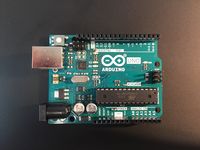
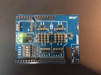
Required hardware components
Required software
- Serial terminal program with logging capabilities. We recommend Putty which is available on Windows/Linux/Mac.
- Math program capable of importing numbers from a text file. Matlab or Octave (free) is recommended, but Microsoft Excel can also be used.
- Arduino sketch (C/C++ program for the Arduino) File:Veltek-shield-motor-ab-encoder.zip that starts the DC motor and count pulses from the encoder on the motor.
- Important: After unpacking the .zip file, make sure that the folder name is the same as the .ino file name inside. E.g.: veltek-shield-motor-ab-encoder.
- Arduino IDE to compile and upload the sketch to your Arduino. This is available on Windows/Linux/Mac
Setup
- Mount VelTek shield on top of Arduino. Take care that all pins mate correctly to their sockets before pressing together.
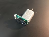
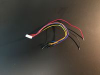
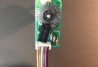
- Connect motor cable to DC motor. The little white plug can only go in one way. When inserted correctly, the orange wire is towards the edge of the circuitboard. (See picture)
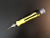
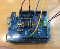
- Use screwdriver to connect the red wire to "OUTB" and black wire to "OUTA" on the green terminal on VelTek shield. The red and black wire is for motor voltage that drives the DC motor.
- Connect blue wire to Arduino GND, and yellow wire to Arduino 5V. These wires power the encoder circuit on the back of the motor.
- Connect violet wire to Arduino pin 3 and orange wire to pin 2. These wires carry the output signals from the encoder on the motor.
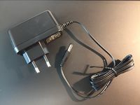
- Plug the AC/DC adaptor into a 230V wall socket and then insert 12V plug from adaptor into the Arduino.
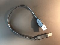
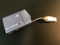
- Optional but reccomended: Connect Arduino board to USB hub.
- Connect Arduino or USB hub with Arduino to your computer.
Note: Make sure that you connect the 12V adaptor to your Arduino board before connecting it to your computer via USB.
Usage
Getting started
When the Arduino sketch has been compiled and uploaded, you can check that it is running by opening the serial monitor in the Arduino IDE (icon in top left of the window). When window opens, make sure that you have chosen "115200 baud" as communication speed in drop down menu. You should see two columns of nubers on the screen.
To test that motor and encoder works, try to turn the motor axel by hand. You should see the number in the first column increase og decrease. The number is motor position in milli radians (6283 milli rad / turn)
Click on the text box in top of the serial monitor window, type the string "v5000" and press enter. The motor should start turning. The number is voltage in millvolt (12 V = 12000 mV). Type "v0" and enter to stop the motor (0 V)
Serial commands
   r -reset encoder value
   f<n> -where n is the wave form frequency in deci-hertz (1/10th Hz)
   v<n> -where n is the desired DC motor voltage in millivolt. Range: -12000 >= n >= 12000
   u<n> -where n is the desired wave form amplitude upper value in millivolt. Range: -12000 >= n >= 12000
   l<n> -where n is the desired wave form amplitude lower value in millivolt. Range: -12000 >= n >= 12000
   t<n> -where n is the desired wave form type. 1=sine, 2=triangle, 3=step function
Creating velocity feedback
Every line of code inside the Arduino function void loop() (bottom of Arduino sketch file veltek-shield-motor-ab-encoder.ino) will be executed repeatedly as fast as possible, but we don't have any control over exactly how fast. This is bad for control systems where we want to know the sample rate in Hz. An easy fix is to create a function that can measure if a fixed amount of time has passed. This is exactly what checkTime() does. It returns true if 4 ms (or more) has passed and false otherwise. You can find this if(checkTime()) statement in the void loop() function:
if(checkTime())
{
   Serial.print(motorpos);
   Serial.print(" ");
   Serial.println(motorcmd);
}
This is responsible for printing out the two columns of numbers (position in milli radians and motor voltage) at a rate of 250Hz (4ms period). If you want to create a feedback system, you can add code here to calculate an error, multiply it with a gain, and feed it to motor.setMotorVoltageMilliVolt().
Interresting functions for creating a feedback control system could be motor.getMotorPositionAngle() and motor.getDeltaMotorPositionAngle(). You find available functions declared in the header file VTMotorControl.h.
Problems??
- Problem: The numbers in the first column (motor angle) never changes, or can only increase.
- Solution: The encoder signals (purple and orange wire) are probably not connected correctly. They should connect to the pin directly next to the little grey wire. Click on the close-up picture of the board to view it in large format and double check all connections.
Hardware description
Electrical schematic for VelTek shield: File:Arduino Shield Veltek02 19032019.pdf
Info on motor: File:Mayitr DC6V 12V 130 Motor 7800RPM Mini Motor with Metal Speed Encoder Tachometer Motor AB Phase reduced.pdf
Software description
The Arduino sketch volte-shield-motor-ab-encoder consists of four files:
- veltek-shield-motor-ab-encoder.ino
- Main sketch file with the two important Arduino functions setup() and loop() plus some extra utility functions to help the system measure and keep sample time and read user input/commands form the serial port.
- VTMotorControl.cpp (and .hpp)
- Implementation of the motor control functions
- VTSerialParser.cpp (and .hpp)
- Helper functions that converts a received number on the serial port to an integer.
- VTShieldPins.h
- Pin and signal definitions for VelTek shield.
- VTWaveFormTables.h
- Tables for sine-wave, triangle-wave and step.
