Difference between revisions of "VelTek shield motor step"
Jump to navigation
Jump to search
(→Setup) |
|||
| Line 28: | Line 28: | ||
= Setup = | = Setup = | ||
# Connect VelTek shield to Arduino | # Connect VelTek shield to Arduino | ||
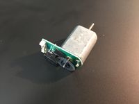
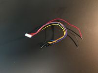
| − | # Connect motor | + | # Connect motor cable to DC motor. The little white plug can only go in one way. When inserted correctly, the orange wire is towards the edge of the circuitboard. (See picture) |
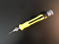
| + | # Use screwdriver to connect red and black wire from motor cable to the green terminal on VelTek shield. The red and black wire is for motor voltage that drives the DC motor. | ||
| + | # Connect blue wire to Arduino GND, and yellow wire to Arduino 5V | ||
| + | # Connect violet wire to Arduino pin | ||
| − | |||
= Hardware description = | = Hardware description = | ||
= Software description = | = Software description = | ||
Revision as of 14:01, 9 May 2019
Contents
Required hardware components
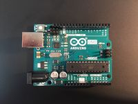
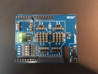
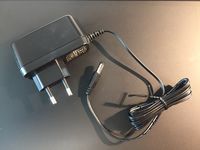
To complete this exercise you need for following:
Required software
- A serial terminal program with logging capabilities. Putty is available on Windows/Linux/Mac and is recommended
- Math program capable of importing numbers from a text file. Matlab or Octave is recommended, but Excel can also be used.
Setup
- Connect VelTek shield to Arduino
- Connect motor cable to DC motor. The little white plug can only go in one way. When inserted correctly, the orange wire is towards the edge of the circuitboard. (See picture)
- Use screwdriver to connect red and black wire from motor cable to the green terminal on VelTek shield. The red and black wire is for motor voltage that drives the DC motor.
- Connect blue wire to Arduino GND, and yellow wire to Arduino 5V
- Connect violet wire to Arduino pin
